>>  Technologies

>>  Products

>>  Specs & Prices

>>  Shopping Cart

>>  Forum

>>  Contact Us

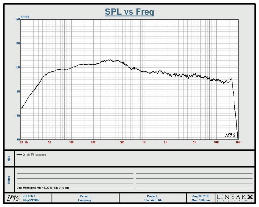
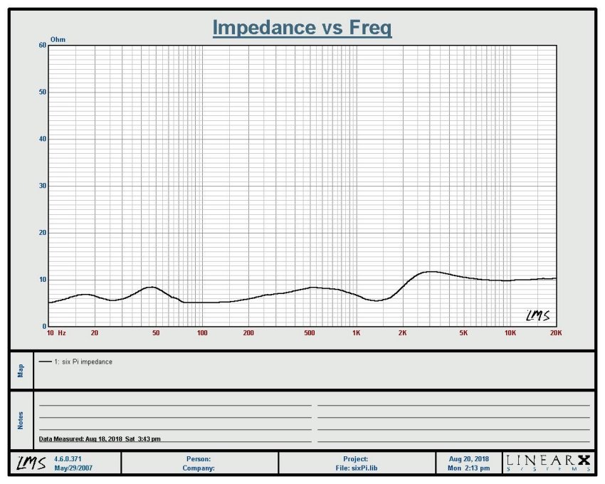
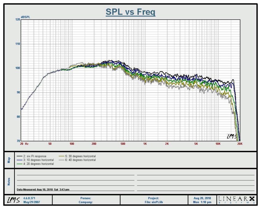
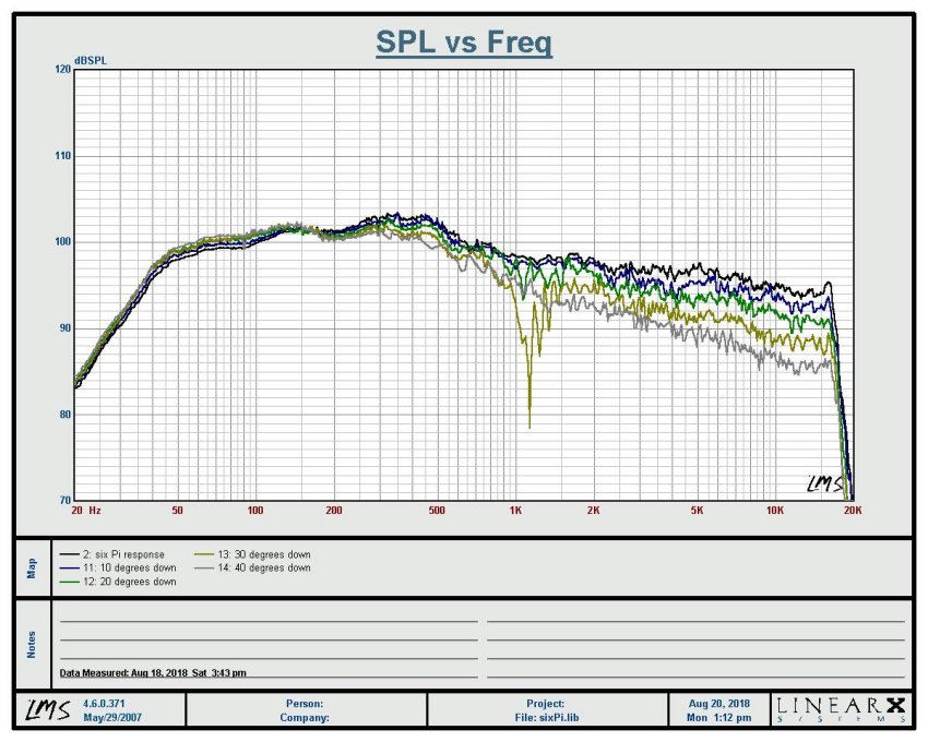
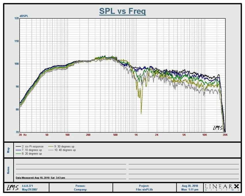
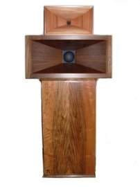
six π constant directivity cornerhorn performance data

six Pi cornerhorn


The ideal: The constant directivity cornerhorn. In this configuration, the sound source is within 1/4λ from the apex of the corner. This makes the walls act essentially as a large waveguide, confining radiation to the angle of the walls. There is no waveform disturbance - It creates a perfect section of a purely spherical wavefront from the corner into the room.

Our six "π" constant directivity cornerhorn is the result of decades of refinement and hundreds of hours of extensive development and testing. It provides high-fidelity and uniform directivity, and is efficient enough to provide room-filling sound even when driven by low-powered single-ended triode amplifiers. It also has the thermal capacity to handle several hundred watts of amplification without distortion or stress. This wide range of power levels provides exceptional dynamic range, making the six "π" constant directivity cornerhorn suitable for critical listening, studio monitoring and home theater applications.

Bass extension is more than adequate with or without subwoofers, but the use of multisubs smooths the modal region while simultaneously increasing deep bass extension. A pair of subs placed at opposite ends of the room from the cornerhorns are recommended for deep smooth bass.

Frequency Response

Impedance

Horizontal Off-Axis Response

Vertical Off-Axis Response (down)

Vertical Off-Axis Response (up)

Notes:

  • All measurements were done in a tridedral corner, with concrete walls extending twenty feet from the apex. The walls were twelve feet tall and the area beyond the walls was open outdoors.
  • Measurements were taken at a distance of two meters (78") from the baffle and drive voltage was 5.66vrms. This is equivalent to 2.83v/M and 1W/1M values since average impedance is 8Ω.
  • Off-axis measurements were done at 10° increments. The zero-degree forward axis was measured directly between midhorn and tweeter, 50" above the ground. Downward angles position the microphone closer to the woofer and further from the tweeter. Because of this relatively close microphone placement, amplitude changes are affected as much by proximity as they are from directivity. Vertical measurements at this distance serve mostlty to show null angles.
  • The 2-meter measurement distance was chosen because it is the maximum distance that a 40° downward arc would support. Greater measurement distance would reduce the downward angle possible because of obstruction from the ground.
  • The loudspeaker was driven with a 60Hz sine at 10vrms to pre-heat for 15 minutes immediately before measurement. This was done to bring it to a realistic operating temperature.
  • No post-processing or smoothing was applied.

π Speakers Open Forum
Where Builders, Buyers, Owners and Users meet online

Email for a Quote or for More Information

Helpful Documents and Software

π Speaker Whitepaper explains the concepts and evolution of modern waveguide and constant directivity loudspeakers
π Speaker Crossover Document analysis of circuits used in waveguide and constant directivity loudspeakers
"Crossover Electronics 101" Seminar Handout
JBL Professional Sound System Design Manual
Passive Crossover Spice models, complete with the AIM Spice modeling program
Pialign Analysis Software to help you design your enclosures. This is the old Altair original from 1977.
Plot the response curve of your design with Carlson's BoxPlot program
Plot the response curve of horns with the HornResp program
Convert Metric and Imperial measurements with the Madison Measurement Converter

[ Technologies ] [ Products ] [ Specs & Prices ] [ Shopping Cart ] [ Forum ] [ Contact Us ] [ Home ]

Pi Speakers and the π Speakers logo are trademarks of π Speakers and may not be used without permission.
© π Speakers. All rights reserved.